
How to Choose a Cordless Puncher for C-Channel, Angle Iron, Sheet Metal and Tube
A practical guide to matching a cordless puncher to C-channel, angle iron, sheet metal, or tube work based on material, profile shape, hole requirements, and job conditions.
Selecting a cordless puncher by brand name, motor power, or a single hole diameter can create avoidable problems.
The most useful starting point is the actual workpiece:
- What is it made of?
- What is its cross-sectional shape?
- Where must the hole be located?
- How thick is the material?
- How can the workpiece be supported during punching?
- How much clearance is available around the hole?
These details determine whether the punch head can reach the required location, whether the punch and die can be positioned correctly, and whether the requested hole geometry is practical for the application.
For contractors, distributors, fabricators, and project purchasing teams, a workpiece-first approach makes technical communication much clearer.
Instead of asking only for “a cordless puncher,” provide a drawing and a short set of job details. The supplier can then assess a suitable punch head, die arrangement, and, where relevant, an adapter or custom solution.
Start With the Workpiece, Not the Tool Body
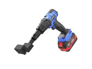
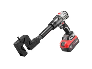
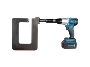
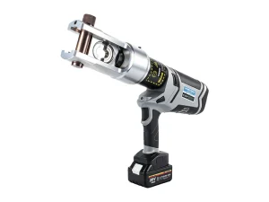
A cordless puncher is a complete system.
The tool body provides the drive, while the punch head and punch-and-die arrangement determine how the tool interacts with the workpiece.
Two jobs may require the same nominal hole size but still need different configurations because the profile edge, return lip, wall shape, or available clearance is different.
Why the Same Hole Size Does Not Mean the Same Puncher
For example, a 10 mm round hole may be required in:
- Flat sheet metal
- Angle iron
- C-channel
- Aluminum profile
- Round tube
Although the hole diameter is identical, the surrounding geometry can be completely different.
The punch head must be able to:
- Reach the required hole position
- Enter the profile correctly
- Position the punch and die
- Clear nearby flanges, ribs, bends, or lips
- Support the workpiece correctly during punching
Therefore, hole diameter should be treated as one specification rather than the entire selection criteria.
DEJIN MASTER Tooling Series
The DEJIN MASTER catalog includes dedicated tooling families for applications such as:
- C-shaped steel
- Electrical-installation materials
- Angle iron
- Aluminum alloy profiles
- Keel profiles
- Sheet metal
- Tubular materials
These product families provide useful starting points for comparing possible configurations.
However, they should not be treated as universal compatibility statements.
Each configuration has its own material, thickness, hole, head, die, and application parameters. The final choice should always be checked against the specific workpiece.
Confirm These Four Points Before Requesting a Quotation
Before asking for a cordless puncher recommendation, prepare four categories of information.
1. Material and Thickness
Identify the material accurately.
For example:
- Steel
- Coated steel
- Aluminum profile
- Electrical tray material
- Tubular steel
- Other specified metal
Then provide the actual material thickness.
If relevant, also provide:
- Material grade
- Coating
- Surface treatment
- Protective film
- Other material conditions
Thickness alone may not provide enough information when material properties or coatings can affect the punching result.
A drawing, section sketch, or clear sample photograph makes the inquiry more reliable.
2. Profile Shape and Access
Describe the cross-section and identify the punching side.
For example, is the hole located on:
- Side flange
- Base flange
- Flat face
- Edge
- Curved wall
Also identify any:
- Return lip
- Rib
- Fold
- Weld
- Bend
- Nearby obstruction
The geometry around the hole can be just as important as the overall profile dimensions because it affects head opening, throat depth, punch alignment, and die access.
3. Hole Requirement
State the complete hole requirement.
Include:
- Hole shape
- Finished dimensions
- Hole orientation
- Hole position
- Edge distance
- Tolerance, if critical
- Hole spacing
- Number of different hole patterns
Possible hole shapes may include:
- Round
- Oval
- Rectangular
- Slotted
- Double-round
- Other custom patterns
If the project requires multiple hole patterns, state this clearly. It may affect whether a quick-change die arrangement or purpose-made die should be considered.
4. Working Conditions and Quantity
Explain where the punching will take place:
- On site
- In a workshop
- Overhead
- In a restricted installation area
- At a fixed workstation
Also provide:
- Expected quantity
- Holes per workpiece
- Hole spacing
- Number of profile types
- Expected repeat frequency
This allows the selection to account for both the workpiece and the operating process.
Use the Product Series as a Starting Point for Matching the Job
Workpiece or Job Type | Relevant Catalog Direction | What to Provide for Confirmation |
C-shaped steel or U/C-section | C-Shaped Steel Series | Section drawing, punching face, flange/base dimensions, material thickness, and hole pattern |
Cable tray or electrical-installation material | Electrician Series | Tray/profile drawing, coating, wall thickness, and required hole layout |
Angle iron | Angle Iron Series | Leg sizes, thickness, hole position from each edge, and round or oval requirement |
Aluminum profile or drain profile | Aluminum Alloy Series | Cross-section, wall thickness, hole position, and special hole geometry |
Keel or light-profile material | Keel Series | Profile sketch, material thickness, and hole or rivet-hole requirement |
Flat or formed sheet material | Sheet Metal Series | Material, thickness, edge distance, formed features, and hole shape |
Round tube or tubular material | Tubular Series | Outside or internal diameter, wall thickness, hole orientation, and support access |
C-Shaped Steel: Check the Punching Face and Opening Geometry
C-shaped steel work often involves a side, base, or flange location rather than an unrestricted flat sheet.
Start with a section drawing and mark the exact hole position.
The C-Shaped Steel Series includes different head configurations for different C- and U-shaped steel geometries. Therefore, the opening dimensions and punching direction should be assessed before a model is proposed.
What to Show on a C-Section Drawing
Include:
- Overall width
- Overall depth
- Flange dimensions
- Return lips
- Material thickness
- Hole position
- Punching face
- Hole dimensions
If holes are repeated but the profile changes between projects, provide each profile drawing rather than assuming that one punch head will cover every section.
Electrical Materials: Identify the Tray or Profile, Not Just the Application
In electrical installation work, terms such as cable tray can describe different materials, dimensions, coatings, and folded geometries.
Therefore, provide:
- Tray type
- Material
- Coating
- Wall thickness
- Section drawing
- Hole layout
The DEJIN MASTER Electrician Series includes zinc-coated tray examples, but the final selection should be based on the exact tray geometry and hole requirement.
Why Edge Clearance Matters
This is especially important when the hole is located close to:
- Tray edges
- Folded sections
- Flanges
- Reinforced areas
- Other formed features
A puncher that can process the material thickness may still require a different head configuration if the surrounding geometry restricts access.
Angle Iron: Define Both Legs and the Reference Edge
Angle iron requires attention to both leg dimensions and leg thickness.
First identify which leg will be punched.
Then show the hole centerline relative to the relevant edges.
What to Include for Angle Iron
Provide:
- Leg A dimension
- Leg B dimension
- Material thickness
- Hole diameter
- Hole position
- Edge distance
- Punching face
- Hole orientation
If the project uses an oval hole for adjustment, include:
- Oval length
- Oval width
- Orientation
- Center position
The DEJIN MASTER Angle Iron Series provides a relevant starting point, but the final configuration depends on whether the punch head can locate correctly on the selected leg while clearing the adjacent leg.
Aluminum Alloy and Keel Profiles: Drawings Are Essential
Aluminum alloy profiles and keel materials frequently have complex cross-sections, thin walls, or shaped drainage features.
For these applications, a clear section drawing is more useful than a general material description.
DEJIN MASTER lists Aluminum Alloy and Keel Series configurations, including examples intended for profile-specific punching requirements.
Information to Provide
Send:
- Profile cross-section
- Overall dimensions
- Wall thickness
- Hole shape
- Hole dimensions
- Hole position
- Reference dimensions
- Punching face
- Photos of the actual profile
This information helps determine the appropriate support, punch head, and die arrangement.
Sheet Metal: Consider the Area Around the Hole
Flat sheet metal may appear straightforward, but the local area around the hole still matters.
Confirm whether the sheet is:
- Flat
- Folded
- Formed
- Ribbed
- Flanged
Also provide the required edge distance and identify any bends or formed features near the punching area.
Check the Local Geometry
The area immediately around the hole can affect:
- Punch-head access
- Die positioning
- Material support
- Hole location
- Punching direction
The DEJIN MASTER Sheet Metal Series includes configurations for different sheet-material applications, with some configurations identified with quick-change dies.
However, this does not mean that every sheet thickness, hole shape, or formed sheet uses the same die.
The actual job should be reviewed before selecting the configuration.
Tubular Material: Confirm the Diameter and Support Position
Tubular materials introduce a curved punching surface and can require access around or inside the material.
For round tube applications, provide:
- Outside diameter
- Internal diameter, where relevant
- Wall thickness
- Hole diameter
- Hole shape
- Hole orientation
- Hole position
- Support conditions
Why Tube Geometry Matters
The curvature of the tube can affect how the punch and die contact the material.
The application becomes more complex if the tube:
- Cannot be rotated
- Is already installed
- Is close to another component
- Has limited access
- Requires holes at multiple orientations
The DEJIN MASTER Tubular Series contains round-tube examples, but the actual tube diameter, curvature, thickness, and clearance should be confirmed before selecting a punch head.
When to Consider Quick-Change Dies, Custom Dies, or Adapters
Not every application requires custom tooling.
The correct choice depends on how closely the job matches the available standard configuration.
When to Consider Quick-Change Dies
A quick-change die arrangement may be useful when:
- The applicable configuration is designed for quick die changes
- The workpiece geometry remains the same
- Different compatible hole sizes are required
- Operators need to change hole specifications during production
Always verify the available die range and compatibility for the specific punch head.
Do not assume that a die from one configuration will fit another model.
When to Consider a Custom Die
A custom die may be worth discussing when:
- The hole shape is non-standard
- The hole position is unusual
- The profile section is outside standard configurations
- A special punching direction is required
- A specific hole pattern is repeated in production
A useful custom-die inquiry should include:
- Dimensioned drawing
- Material type
- Material thickness
- Hole geometry
- Hole position
- Expected quantity
- Photos
- Workpiece sample, where available
When to Consider an Adapter
The DEJIN MASTER catalog also includes an Adapter Series.
An adapter may be relevant where a verified configuration requires a particular connection or setup.
However, an adapter should never be selected by appearance alone.
Before ordering, confirm:
- Tool-body interface
- Punch-head interface
- Applicable configuration
- Compatibility
- Intended working conditions
Prepare an Inquiry That Can Be Engineered, Not Guessed
For the fastest and most accurate recommendation, prepare the following information:
Workpiece Information
- CAD file, PDF drawing, or clear dimensioned sketch
- Material type
- Material thickness
- Full profile section or tube dimensions
Hole Information
- Hole shape
- Hole size
- Hole orientation
- Hole position
- Reference dimensions
- Hole spacing, if applicable
Project Information
- Workshop or site conditions
- Expected quantity
- Repeat-production requirements
- Photos or a physical sample for complex profiles
With this information, DEJIN MASTER can check whether the project is more suitable for:
- A standard punch head
- A compatible quick-change die arrangement
- A custom die
- An adapter-supported configuration
Choose the Cordless Puncher Around the Workpiece
The right cordless puncher is not simply the model with the highest punching force or the largest advertised hole diameter.
It is the configuration that matches the:
Workpiece + Material + Thickness + Profile Geometry + Hole Requirement + Working Conditions
A C-channel, angle iron, sheet-metal panel, aluminum profile, and round tube may all require holes, but the correct punch-head configuration can be very different.
Start with the drawing.
Confirm the technical fit.
Then select the tool system.
This workpiece-first approach can help reduce the risk of purchasing a configuration that looks suitable from its basic specifications but does not physically match the actual application.
Talk to DEJIN MASTER About Your Workpiece
Send your profile drawing, material details, thickness, hole pattern, expected quantity, and working photos to DEJIN MASTER.
Our team can review the applicable product series and help determine whether a standard punch head, compatible quick-change die configuration, custom die, or adapter solution should be considered for your project.